
Editor’s Note: Welcome to Cadalyst's blog series by Patrick Hughes, A CAD Dinosaur's Journey into Modern Times.” In this three-month series, Hughes chronicles his transition from AutoCAD R14 to v2015 and from an outdated PC to a state-of-the-art professional workstation. Follow along and enjoy!
 You may have guessed it — this Dino really enjoys working with 3D solid models. I recently worked on a project that involved a few molded parts and the mold maker worked from my solid model. The advent of 3D printing in the manufacturing process is already reducing the need for 2D drawings in some situations. You can easily export your solid models in AutoCAD to the STL file format for 3D printing. (For best file resolution when 3D printing, set your FACETRES system variable to 10.)
For the most part however, we need 2D drawings and AutoCAD 2015 does not disappoint in its capabilities. Coming from an antiquated AutoCAD Release 14 installation I was familiar with the Soldraw, Solprof, and Solview viewing commands that projected my views onto a flat plane. I enhanced my use of these commands with several custom AutoLISP programs to create my orthographic views along with “squashing” my pseudo 3D inserts. This served me well for awhile, although there were occasions when the final drawing required more involved clean-up operations.
I’m glad to see that over the years AutoCAD has added functionality that makes these cleanup operations easier. One such function is the Overkill command. Originally an Express Tool, but in AutoCAD 2012 it became a core AutoCAD command, Overkill deletes duplicate objects as well as combines overlapped lines.
A couple of other commands that help turn a 3D solid into a 2D drawing are Flatten and Flatshot. Flatten converts 3D geometry into polylines. It works a little bit differently than I expected in that it seems to flatten objects from your line of sight, so if you are in an isometric view you get an isometric projection and the resultant z-values are zero from your current viewpoint. This can be a useful command for creating a flattened isometric or perspective drawing. (I wonder how they came up with that command name.)
Flatshot differs from Flatten in that it produces a block you can insert into your drawing or export out to a file. Again, Flatshot creates the flattened geometry based on your current view. With Flatshot your solid model remains intact but it will only work with 3D solid objects.
The Big Kahuna for getting 2D drawings from a 3D solid model is the Viewbase command. Introduced in AutoCAD 2012, Viewbase really lets you create orthographic projections of your solid model on the fly. Once you select your solids, it creates a base view — letting you specify the orientation of the view (top, front, side, etc). After placing the base view, it prompts you to continue to place views including isometric projections. View placement works dynamically so as you move your cursor away from the base view you see a preview of the resulting geometry for the new view projection.
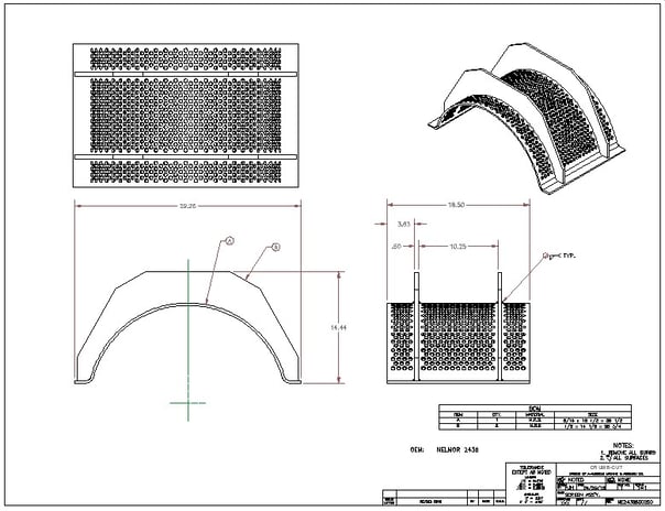
Here's an example of a 2D drawing made with Viewbase.
But that’s not all, folks! You can also create the views from Inventor file types such as IAM, IPT, and IPN. But wait, there’s even more! AutoCAD's views are dynamic, giving you a preview of the projections as you make updates. This makes it easy to make changes, and you don't have to recreate your views because they update as you work. Within the Viewbase command, you can also control the appearance of hidden lines, visibility of things such as tangential lines, interference edges, and additional features depending on your model source.
One drawback I’ve encountered with Viewbase is that, like Flatshot the command only works with 3D solids and the projected views do not include other types of objects. This may not be a problem most of the time and in the example image above it is not a factor. But, when I work with fastener and hole blocks as I discussed in A CAD Dinosaur's Journey, Part 12: Graduate to Dynamic Blocks, it is an issue. Let's just say it presents an opportunity to further develop my customization skills. Thankfully the Solview commands are still available, but I hope to move away from them permanently soon.
Rawrrr!
Wow, how much more dynamic can Autodesk make AutoCAD? I’m willing to bet a lot more. As you know, drafting was developed to convey one’s thoughts to another by means of drawing objects in a standard fashion onto a sheet of paper. With the advent of CAD, 3D models, 3D printing, and so on, how long will it be until designs can be produced from brain waves and mental projection? I guess when that day comes, we’ll all be dinosaurs.
_________________
About the author: Patrick Hughes, machine designer and owner of Engineered Design Solutions in Rockford, Illinois, has worked with AutoCAD since 1991. He has developed a number of AutoLISP and other software solutions to automate his workflow and increase productivity, including the commercially available time tracking program, CadTempo.


