
Editor’s Note: Welcome to Cadalyst's blog series by Patrick Hughes, A CAD Dinosaur's Journey into Modern Times.” In this three-month series, Hughes chronicles his transition from AutoCAD R14 to v2015 and from an outdated PC to a state-of-the-art professional workstation. Follow along and enjoy!
 Who would think something with the name "constraints" could actually be liberating? Well, with arms as short as mine, I find that my reach can be enhanced with constraints. Now, I don’t mean that it’s any easier to grab something from the floor, that’s still a struggle, but while playing around with constraints on a recent project, I found them to be a useful addition to AutoCAD (new in AutoCAD 2010).
At this point I’m just getting my big old T-Rex feet wet with them, but even at this early stage I can see how powerful they are and how they can be used. For my first application of constraints I applied them to a repetitive design task that I encounter periodically. In this case, I had to vertically feed a flanged cylindrical object by means of a set of four helical feed screws. Each job had varying diameters of the cylinder body, and the stack diameter. In most all cases, the flange width was relatively constant and in all cases the feed screw diameter was constant.
In the past I created the circles representing cylinder parts and from that geometry created the clearance offset, and then the offsets for the centers of the feed screws. It sounds simple enough and it was, mostly. It begins to get complicated when multiple cylinder stacks must be fed in close proximity to each other and this is where I thought constraints could help my workflow.
After creating my constrained geometry, I inserted the drawing into my working drawing and finished my design in no time. Since I knew I'd use this infrequently (and this Dino has a terrible memory), I wrote myself some operational notes.
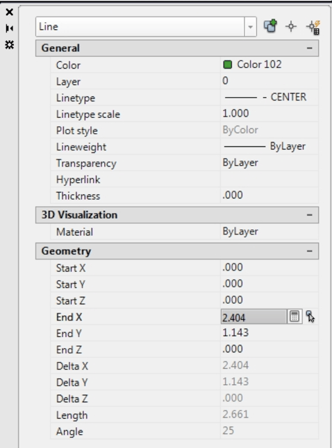
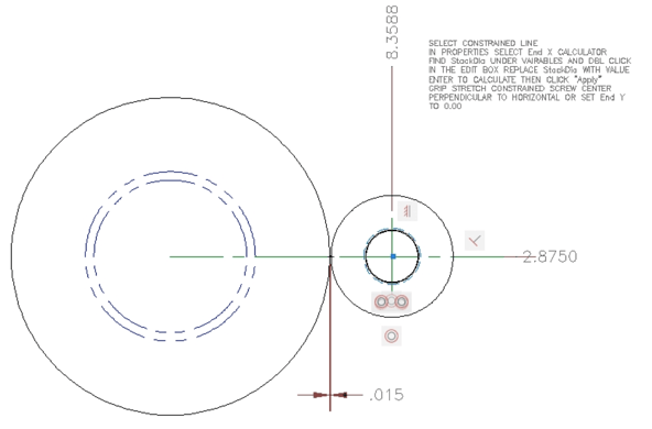
As you can see I also incorporated the Properties Palette and Calculator into my instructions. Within the Calculator you can add variables that can be recalled as well as adding formulas. Following my instructions, I select the line that connects the base circle and the feed screw diameter, and then click on the Calculator icon next to the “End X” in properties.
This brings me to the Calculator.
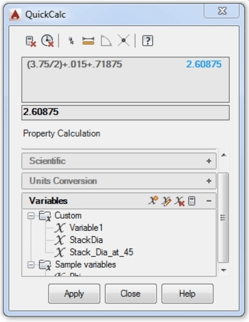
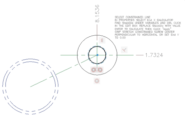
My StackDia variable is a formula that contains the StackDIA that will need to be overwritten with the desired value, the clearance value (0.015) between the stack diameter and the feed screw, plus the radius of the feed screw (0.71875). After entering my stack diameter and calculating, I am prompted to apply the result to the “End X” and at that point the constraints take over and the geometry associated with the lead screws are repositioned. Because this will just calculate the X component of the geometry, I need to set Y to 0.00.
The resulting geometry shows the clearance after I add the 3.75 stack diameter circle. You can also see that I’ve used Associative Dimensions that update when there is a change to the geometry. In this case the origin for the ordinate dimensions is off screen.
All of this is easy enough with plain old AutoCAD, but now that I’ve got my geometry constrained, I can begin positioning the remaining lead screw by making copies and rotating. The example of a completed detail shows the final positioning for two cylinder stacks along with additional geometry considerations.
Rawrrr!
I can feel my arms stretching every time I start a new AutoCAD drawing. I may not have a complete handle on everything 2015 has to offer, but I’m making my way. There’s a couple of glitches in my cylinder-feed screw constraint application but a little tweaking and experimentation will make for a very toothy grin.
_________________
About the author: Patrick Hughes, machine designer and owner of Engineered Design Solutions in Rockford, Illinois, has worked with AutoCAD since 1991. He has developed a number of AutoLISP and other software solutions to automate his workflow and increase productivity, including the commercially available time tracking program, CadTempo.


