When NASA first enabled humanity to walk on the Moon, lunar exploration was an end unto itself. Now NASA is deep into preparations for Moon 2.0. This time, traveling to the Moon will become the first step for greater ambitions, as it becomes a staging area for further exploration and eventually sending a human crew to Mars.

NASA is doing this new round of exploration — the Artemis mission — based on 21st Century expectations, budgets, and technology. According to NASA administrator Jim Bridenstine, the space agency and its supply chain partners will accomplish an ambitious agenda with half the buying power it had back in 1964, when Apollo development was at its peak. Looking for every advantage, one major contractor is using the latest additive manufacturing (AM) technology and CAD to create an advanced rocket subassembly.
Los Angeles-based Aerojet Rocketdyne was a leading manufacturing contributor for the Apollo missions, and is back as a contributor to Artemis, developing guidance thrusters for the Artemis lunar lander. “As with any complex endeavor, the more affordable you can make it, the greater the chance that you will ensure its completion, and the Moon is no different,” said James Horton, aerospace engineer and mission architect at Aerojet Rocketdyne. “Metal additive manufacturing plays a key role in achieving these goals.”
Building on a Legacy
For more than two decades, Aerojet Rocketdyne has invested time and resources on using AM, focusing most of its energies on laser powder bed fusion (LPBF). Aerojet Rocketdyne has designed and integrated 3D-printed end-use components for a variety of projects, among them the massive RS-25 engines that will carry the Artemis mission into space.
LPBF applies thin layers of metal powder to a build plate, then uses a laser to fuse the powder, using geometry from a CAD model to guide the process. There are variations of the process on the market, including selective laser sintering (SLS), selective laser melting (SLM), direct metal laser sintering (DMLS), direct metal laser melting (DMLM), and electron beam melting (EBM).
Since 2008, Aerojet Rocketdyne’s Horton has participated in several lead roles in rocket engine design, development, and test flight operations for NASA and the DOD. His advanced propulsion team at Aerojet Rocketdyne is currently working on chemical, electric, and nuclear propulsion to support NASA's deep space exploration efforts, in addition to the Artemis project.
Horton says that using metal AM in conjunction with advanced design and simulation software gives today’s aerospace engineers “an entire buffet of solutions that were completely unavailable to their predecessors, providing the unparalleled ability to innovate without compromise.” Because of this, Aerojet Rocketdyne has been able to drive down propulsion costs, speed up time to market, and improve product performance.
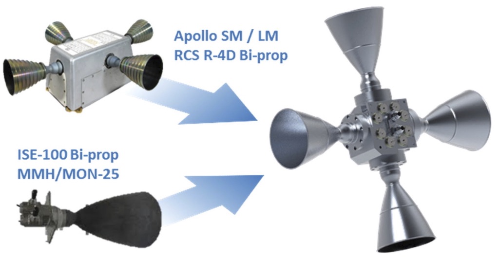
One recent example of this innovation is for a critical subsystem that Apollo engineers knew as a “quad” reaction control system (RCS). The Apollo RCS included four individual R-4D bipropellant thrusters, originally designed by Marquardt Corp., that used hypergolic (spontaneously igniting) nitrogen tetroxide and hydrazine as propellants. Every lunar lander and service module had four quads, each of which generated more than 100 pounds of thrust to control the spacecraft’s roll, pitch, and yaw during flight. Following a series of acquisitions, Aerojet Rocketdyne eventually took ownership of the R4-D, intending to use what is now called the “reaction control system” (RCS) on the future spacecraft.
The first 3D-printed version of the revamped R-4D reaction control system was a huge improvement over its predecessor, but moving from a nickel alloy to titanium made it even better. Image source: Velo3D.
Because the original RCS design is more than 60 years old, Horton and his team recognized an improvement opportunity and began what would become one of the many internal research and development (IRAD) projects intended to optimize the systems required for the Artemis program and other commercial lunar projects. In the case of the RCS, they looked for ways to reduce the number of engine parts, increase its reliability, and make assembly and serviceability easier, all of which would decrease project costs while enhancing spacecraft performance. Metal AM checked all these boxes.
“During the entire Apollo program, NASA produced more than 650 thrusters to support six Moon landings,” said Horton. “It was a huge number, which led us to believe we were onto something big. We knew that if we could bring affordability to the RCS, we could make a positive impact on this and future programs.”
The Aerojet Rocketdyne team also wanted to take advantage of rocket fuel advancements. Horton says propulsion engineers learned over the years that adding 25% nitric oxide to the original fuel oxidizer (nitrogen tetroxide) would reduce its freezing point from −9 °C (16 °F) to −55 °C (−67 °F). Lowering the freezing point reduces the mass and power consumption of the heating systems needed to prevent frozen fuel lines in space. This presented Aerojet Rocketdyne with a significant opportunity. There was just one problem: the fuel (known as MON-25) is unstable, a condition that Horton suggested is a “bad thing to have in rocketry.”
Proving the Concept
Fabricating with AM provided a path to the stability solution. Using LPBF allowed the team to print special injector geometries that could burn the fuel in a stable manner. They soon designed and built a concept model from the nickel-based superalloy Inconel 718, but ran into limitations with their existing metal 3D printer.
“We had to build the RCS injector body at a 45-degree angle, due to overhang concerns, and also add in a series of large support structures to prevent thermal warping during the build process,” Horton said. “The supports would need to be machined away afterward, adding cost to the product, while the orientation angle created less than desirable surface quality. There was definitely room for improvement.”
At the same time, they realized there was room for substantial lightweighting and topology optimization. Horton noted that they’d eliminated “large chunks” of unnecessary material during the redesign, but it was far from perfect. “Every single pound of material you can remove from a spacecraft saves money on launch costs,” he said. To take their design to the next level, Aerojet Rocketdyne turned to software developer nTopology and 3D printer vendor Velo3D.
Shell, Fill, and Print Again
nTopology is a next-generation CAD tool designed specifically for the kind of advanced engineering and manufacturing problems encountered in Design for Additive Manufacturing (DfAM). Technicians from the New York-based company were quickly able to “shell out” the injector body’s blocky structure, leaving consistent wall thicknesses around the complex fluid ports and channels while eliminating stress concentration areas. Then they filled the resultant void with a thin lattice structure, increasing its strength and stiffness while adding only minimal weight. nTopology uses implicit modeling (automated calculation of model details), which the company says allowed designers to cut the quad injector’s mass by half.
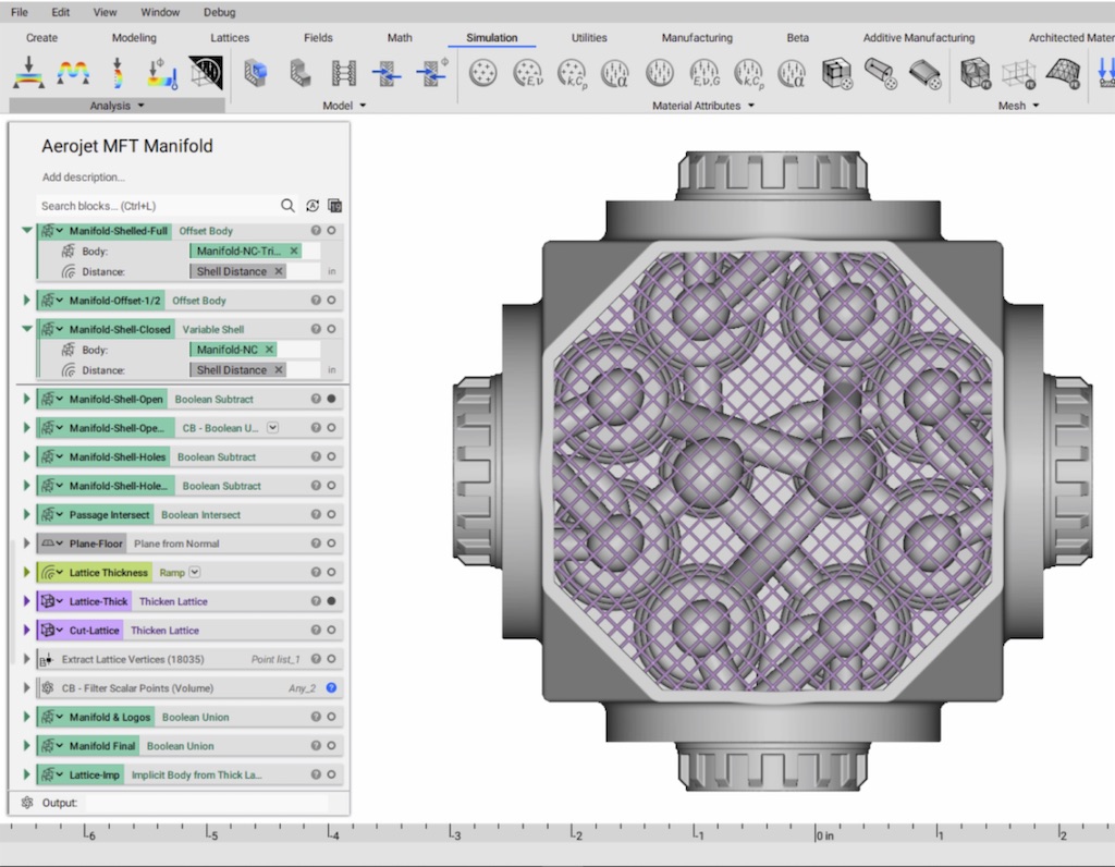
nTopology’s implicit modeling function was able to quickly “shell and fill” the injector body’s first design iteration, increasing its strength and printability while greatly reducing weight. This design was then used to create the titanium model. Image source: nTopology. Click image to enlarge
The Aerojet Rocketdyne team sent the optimized part file to AM vendor Velo3D for the next stage of the redesign. The Campbell, California company is one of the few 3D printing vendors with titanium capabilities. Titanium is favored in aerospace for its combination of strength and light weight. Velo3D was able to show the Aerojet Rocketdyne team how the RCS injector body could be printed with the lighter and stronger titanium instead of the nickel alloy they were using, and that it could be printed without odd angles or blocky support structures.
“Our proprietary, pre-print software is intuitive enough to recognize different geometric features and apply specific laser parameters to those areas so that they print as efficiently as possible and without the need for added support material,” says Gene Miller, technical sales engineer at Velo3D. “In addition, we’re one of the few metal AM system providers that can successfully print large complex titanium parts without cracking. We have a unique solution to mitigate accumulated internal stress within the printed material, and can avoid cracking more so than other printers on the market.”
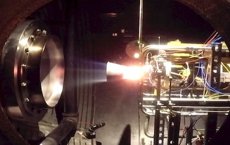
The titanium thruster shown here was 3D-printed on Velo3D’s Sapphire system. Titanium proved to be lighter, smaller, and more cost-effective to build than any other available solutions. Image source: Velo3D.
Thanks to advanced CAD and a new approach to 3D printing, Aerojet Rocketdyne now has an RCS thruster that is 1/5 the mass, 1/2 the size, and 1/3 the cost of a conventionally manufactured version. And, since it contains far fewer components, it’s also easier to assemble, with much less chance of failure during operation.
“We’ve shown that by leveraging additive manufacturing and advanced software technology, we’re able to interject affordability, reduce lead times, and greatly improve upon system performance compared to the way we built parts in the past,” says Aerojet Rocketdyne’s Horton. “Our next step is to demo this proof of concept, bringing it into actual field testing and, hopefully, final qualification. From there, it's headed into space.”
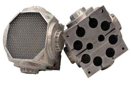
The final version of Aerojet Rocketdyne’s “Mk. II” RCS injector block, shown in its as-built orientation. Image source: Velo3D.
Read more about Additive Manufacturing:
Additive Manufacturing, Part 1. AM Leads Production to New Heights. Find out what additive manufacturing is, how it’s used, and where the technology is leading.
Additive Manufacturing, Part 2: Who's Who and What's What in 3D Printing. The 3D printing arena includes a variety of players: from small to large, will-known companies. Find out which companies are using technology that will work for you.
Additive Manufacturing, Part 4. Increasing Innovation and Reducing Inventory with Additive Manufacturing. Case Study: When these two companies hit roadblocks in their design process, they turned to 3D printing.

Searching for more information about Product Design & Manufacturing?
Click here!