
From its origins as the first parametric modeling software for mechanical engineering until today, PTC Creo is synonymous with mechanical and product design. In a highly competitive market, Creo remains widely regarded as a top-tier MCAD solution.
Recently, PTC introduced Creo 11, the latest update to this versatile MCAD portfolio. New features reflect the changing needs of manufacturing, providing engineers with purpose-built tools for such tasks as multibody design, composite design, electrification, model-based design processes, and more.
Collaboration is at the heart of modern engineering practices. Gone are the days of engineering tasks being described as “siloed” activities, in which an engineer designs a part or assembly and then “throws it over the wall” to someone else. Creo 11 enhances its capabilities to integrate processes such as model-based design and simulation-based design into a team workflow.
Design for Electrification
The merging of electrical and mechanical design is a major trend in product development. Creo 11 offers new or improved design tools for designing wiring, harnesses, and circuit boards within the mechanical geometry, not separated from it as in years past.
There are enhancements to the cabling tree, such as markers, tapes, and tie wraps, and expansions to the Remove Locations capability. Context visibility has been improved, giving designers more control over the ECAD context data, such as color and transparency. This improved visualization makes it easier to align electrical components within a mechanical design. Enhanced wire tracing with better selection and highlighting of cabling entities leads to increased efficiencies.
Other specific new features include:
- Changing harness settings during routing
- An improved cabling tree for greater visibility of harness structure
- The Remove Locations capability now allows dynamic preview of cabling in Graphics View, along with expanded filtering and improved Undo/Redo options.
Composites
The use of composites is expanding beyond high-end aeronautics. Creo 11 has a variety of new features to assist in this challenging and important new combination of materials and processes.
Engineers using Creo 11 can access more features around ply transitions, laminate section, and draping simulation. This provides more flexibility and control over the final product’s shape and size. The process uses a new zone-based design approach, which lets engineers create zone stacks — a mix of ply combinations — and apply them to different zones of the design. “This makes conceptual design faster and helps create large-scale composite products,” notes Paul Sagar, vice president of product management at PTC.
For taking designs into manufacturing, Creo 11 supports leading laser projection formats that help users place and position each ply into the mold more accurately. This significantly improves product quality and reduces manufacturing time. In addition, support for core sampling allows users to generate a report of the plies, orientation, material, and thickness for each ply at a certain point. This gives clear references of the design as it is applied in the manufacturing process.
Model-based Definition
In recent years model-based design and model-based definition has proven their value as an improvement in collaborative design. These methodologies are at their best when they help teams improve data organization, communications, and interoperability. They also streamline the process of making data readable to both humans and machines.
Creo 11 offers the ability to create simple tables that can embed semantic references and parameters from the design. This allows design teams to more efficiently and effectively manage data and enhance communication. There are also new semantic query capabilities for inheritance models.
An example of simple tables that can embed semantic references and parameters from the design. Image source: PTC. Click image to enlarge.
Creo 11 supports the latest STEP AP242, Edition 3, which specifies the use of PMI information for improving interoperability and compliance with multiple stakeholders. There is also support for the latest ISO standards in GD&T Advisor; users can increase their standard compliance while simplifying annotations and updates.
Simulation-driven Design
Simulation-driven design is the process of using simulation technology in the earliest design phases to enable faster innovation and reduce late design changes. It is not uncommon for simulation-driven design to lead to options that would never have been considered using traditional design methods.
Creo 11 increases the utility of simulation-driven design in two of its modules. In Creo Simulation Live engineers can now predict heat transfer between solids and fluids in real time, using conjugate heat transfer. In Creo Ansys Simulation Advanced, engineers can apply multi-step time-dependent structural simulation with transient structure.
Creo’s generative design tools have been enhanced with new constraints and loading conditions that inform downstream analysis. There are new minimum feature size constraints, bearing load support, and planar symmetry constraints.
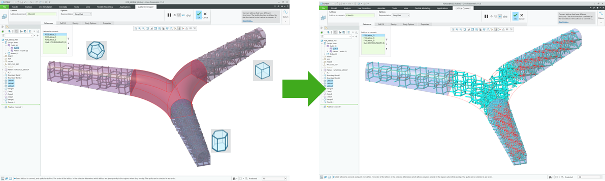
Increased support for 3D printing — AKA additive manufacturing — includes a new Lattice Connect command, which allows for the blending and connecting of multiple lattice volumes to increase design options. Image source: PTC. Click image to enlarge.
Additive and Subtractive Manufacturing
Additive manufacturing technologies (aka 3D printing) continue to offer new and novel ways to create products. The ability to design complex lattice structures is enhanced in Creo 11. A new Lattice Connect command allows for the blending and connecting of multiple lattice volumes for more design options and innovation. For example, improved pore size control for stochastic lattices and support for warp deformation for simplified lattices enable better design of medical implants and filters.
Creo 11 updates previous support for the major 3D printing file formats 3MF and STL, to improve printability of additive models.
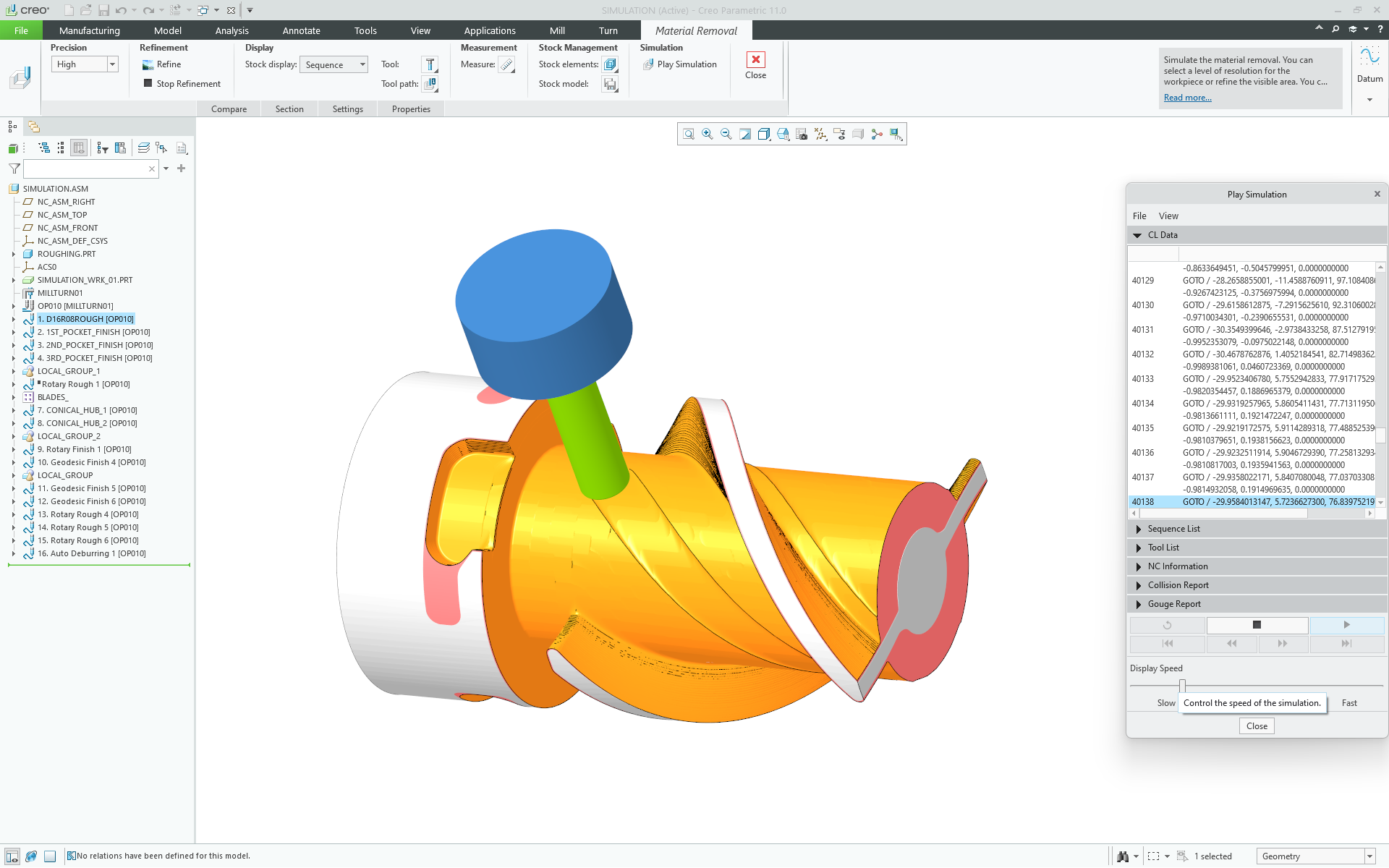
PTC Creo 11 increases support for milling operations, including 4-Axis Rotary roughing and finishing toolpaths, which support end ball and bull nose mills. Image source: PTC. Click image to enlarge.
The rise of additive manufacturing does not mean subtractive processes are going away. Creo 11 expands its high-speed milling features to help cut machining time and improve product quality. An example is 4-Axis Rotary roughing and finishing toolpaths, which support end ball and bull nose mills.
Existing toolpaths in Creo have new features including tangential lead in and out for trajectory milling; increased tool axis control for 5-Axis Trajectory sequences; and better retract plane customization to help drive usability. In addition, a consistent, simplified user interface for 4-Axis Area turning, and improved material removal functionality for profiles, both help the manufacturing workflow and improve the quality of the final part.
Productivity and Usability
A thousand advanced features are useless if engineers struggle to understand how to find and use all the various options. Every update to Creo includes new ways to improve productivity and usability. Creo 11 offers new utility in a variety of settings:
- Multibody workflow offers a new workflow for sheet metal part design.
- Improved Spot Welding offers more flexibility in defining multiple projected point references.
- Working with surfaces is improved, with support for Box, Lasso, and Trace selection.
- Quilts now has a selection priority option.
- A new Shrinkwrap option simplifies collecting bodies from a referenced assembly into a part.
- The process of gathering enclosure volume information for packaging is improved.
The Final View
Creo 11 continues to refine the model-based approach to design. Teams can use it to not only design products but to improve product quality and deliver design data. It supports new technologies and workflows including augmented reality, Industrial Internet of Things, and additive manufacturing. It all adds up to delivering better designs in less time, which makes Creo 11 not only a product design platform but also an engine of innovation.

Searching for more information about Product Design & Manufacturing?
Click here!


Share This Post