Intellitech Srl Consulting Engineers in Timis, Western Romania (Southeastern Europe) designed the Dalli Group’s, one of the most large industrial plants in Europe which produces home products such as laundry detergent. To design the fire safety portion of the 2D and 3D drawings, the company used FineFIRE software from 4M.
The Program — FineFIRE
FineFIRE is a building information modeling (BIM) vertical for fire-fighting design and is part of the FineMEP BIM Suite. It also is DWG- and BIM-compatible with Revit, Archicad, Vectorworks, and SketchUp Pro or equivalent, through the IFC format. It combines design and calculations in an integrated environment, performing all the required calculations for sprinkler installation directly from the drawings, and automatically produces a set of documents: calculation reports, bill of materials (BOM), final drawings (plan views, vertical charts, isometrics, construction details, and the like). FineFIRE adopts the latest NFPA Standard, which outlines world-wide requirements and codes on the design, installation, and maintenance of fixed fire sprinkler systems in buildings. FineFIRE also includes the European Norms (EN 12845), the British Standards (BS 9251), the Australian Standards (AS2118), the South African Standards (ASIB11), the FM GLOBAL, and the CEA 4001 fire protection Standards.
The Case Study
The Dalli Group’s industrial plant is a four-story building with a total area of 6,000 square meters. The plant includes a variety of spaces, including laboratories, warehouse space, meeting rooms, offices and more.
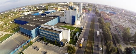
A view of Dalli Group’s industrial plant in Timis, S/E Europe.
With such a large project, the designers had to make sure that the plant had enough sprinklers throughout. When they opened their drawings in FineFIRE and used the Network Design tools, the program automatically proposed the right number of sprinklers for each area, according to their sprinkler types and space hazards. In this situation, there were 780 sprinkler heads placed in total.
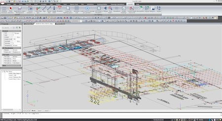
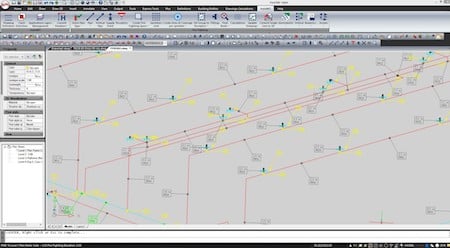
The 3D view of the overall fire piping network.
Next, the software assisted with the piping design process. Designers used a set of routing commands that support any type of network (branches, sub-branches, grids and loops) the connections to the sprinklers.
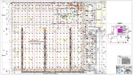
A part of the project with roof sprinklers in a grid, placed automatically by FineFIRE.
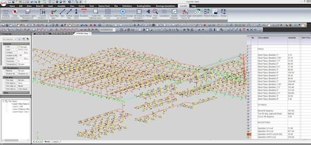
Sprinklers were finally grouped in 92 sprinkler groups, each one covering an area following the design. Then, through the network recognition process, FineFIRE automatically checked the validity of the network, and then highlighted any possible errors and, in each case, suggested how the errors could be fixed, helping to ensure that the calculations were correct throughout.
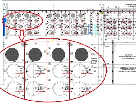
Fire network installation on the ground floor with a detail from the storage tanks space.
The single line model in 3D view.
Standards Compliance
Making sure that the standards are met can be one of the most stressful parts of these types of designs. FineFIRE generated a detailed dimensioning of the piping network, where each pipe was sized in compliance with the NFPA Standard. It detected node numbers and segments and then named and numbered them in order to ensure visibility and easy control in the calculation sheet with respect to the relevant network elements. All parameters such as the maximum area of operation per sprinkler (m2), the design density (mm/min), the friction losses (bar), the flow (liters per minute), and all others according to the NFPA were indicated within the calculation sheets. The designers were also able to edit and adjust parameters if needed, the sheet automatically updated in real-time.
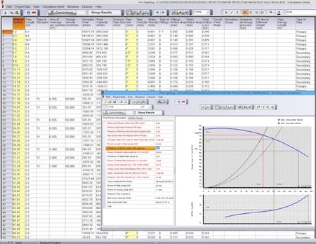
A small part of the "live" calculation sheet (50 nodes out of 780).
In addition, FineFIRE assisted designers by showing which fire pump and water tank to install so that the pump would provide the proper flow and pressure for each branch of the network.
FineFIRE continually updated calculation tables and charts as designers updated the 2D and 3D plant drawings.
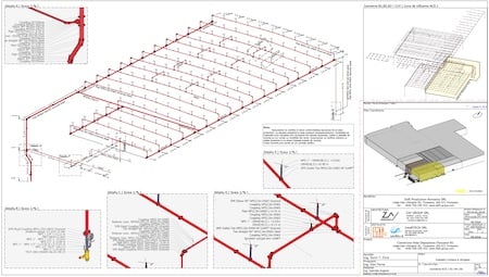
3D axonometric model.
This is where the benefit of using a BIM program shines. The program summarized all the components by type (fittings, pipes, sprinklers, fire pumps, etc.) and the total cost of the firefighting system along with a detailed BOM that updated as the output changed.
Bill of materials and costing.
Conclusions
In this example, designers S. Ficut and D. Ferne from Intellitech Srl Consulting Engineers, successfully designed this large facility using FineFIRE as part of its design software. They state that: The greatest advantage of FineFIRE has to do with the fact that it provides its users with more time and energy to focus on the bigger picture and the higher-level aspects of the design and therefore to reach fast and easier the optimum design solutions, which are well aligned to the client needs.
FineFIRE combines a powerful visualization environment with a strong analytic and modelling framework, which automates the most time-consuming and repetitive tasks of the design process.

Searching for more information about Architecture, Infrastructure, & Construction? Click here!


Share This Post