
In a previous article, we looked at how to create a simple object with Dynamo. Specifically, we created a line in AutoCAD with manually entered point data — not too exciting, but a basic example to demonstrate Dynamo fundamentals.
To expand on that example, let’s look at how we can create more complex objects using point data from other sources. We’ll first draw a polyline using a Civil 3D point group, then draw another polyline using an externally stored point file. As with the previous article, this example will be based on a Civil 3D environment, but most concepts also apply to Revit and other Dynamo-compatible products.
Accessing Point Data in a Civil 3D drawing
To get started, open a Civil 3D drawing and start a new Dynamo session. You will need to have a point group in your drawing to complete these steps.
1. In the Library pane of your Dynamo window, click and expand the Civil 3D category to display additional choices.
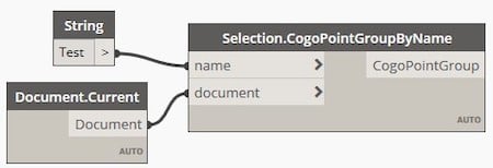
2. Click and expand the Selection category and click CogoPointGroupByName to place a node in the workspace.

Click for high resolution image.
3. In the lower-left corner of the Dynamo window, click the Automatic dropdown and change the run mode to Manual. This allows you to determine when to run the script.
4. Add two nodes to the left of the first node — a String node to provide the name of the point group, and a Document.Current node to connect to the current AutoCAD drawing. (If you need a refresher on how to work with Dynamo nodes and categories, see the previous article.)
5. Click on the Name box inside the Selection.CogoPointGroupByName node and connect it to the empty box in the String node.
6. Connect the Document.Current node to the document box of the Selection.CogoPointGroupByName node.
7. Type the name of the point group in the blank box of the String node. (In this example, the name of the point group is “Test.”) Your workspace should look something like this:
8. Continue adding nodes as follows:
CogoPointGroup.CogoPoints — to generate a list of cogo points from the point group.
Object.Geometry — to convert the Civil 3D cogo points into a list of points understood by Dynamo.
Polyline.ByPoints — to generate an AutoCAD polyline from the list of points.
Document.ModelSpace — to tell Dynamo to draw the polyline in model space.
String — to tell Dynamo on which layer the polyline should be drawn.
9. Type the layer name in the String node (0 in this example) and connect the nodes with “wires” as shown below. You can click on the icons in the upper-right corner to adjust the view of the graph and the background.

Click for high resolution image.
10. From the File menu, click Save to save your Dynamo script with a name of your choice.
11. Click Run in the lower-left corner of the Dynamo window to run your script.
12. Minimize the Dynamo window to display the AutoCAD drawing. You should see a polyline drawn in model space. (You may need to zoom in on the area displaying the polyline.)

Click for high resolution image.
This is still a fairly simple example, and it performs a series of tasks you can also perform with Civil 3D or AutoCAD commands, but it demonstrates how to string multiple tasks together in Dynamo to automate processes.
Accessing an External Point File
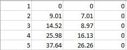
Let’s look at a variation of this example – how to generate a polyline using a list of points in an externally stored file. The points in this example are in comma-separated-value (csv) format, but they could also be in Excel format. This example includes five points, with four columns of data: point number, followed by the X, Y, and Z coordinates. You can easily create a similar file in Excel and save it in csv format.
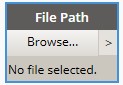
1. In a new Dynamo window, add a File Path node to access the external file. Click Browse to navigate to the file.
2. In the lower-left corner of the Dynamo window, click the Automatic dropdown and change the run mode to Manual. (You can skip this step if you’d rather see Dynamo run the script automatically, as it is developed.)
3. Add the other nodes and connections as shown and described below:

Click for high resolution image.
-
File From Path — to create a file object from the designated path.
-
Data.ImportExcel — to import data from the external file (Excel or csv format).
-
String — to identify the worksheet name in the file (PointFileTest in this example).
-
Boolean — to select whether to read the data as strings (select False in this example).
-
Boolean — to select whether to show Excel when running the script (select True in this example).
-
List.Transpose — to swap rows and columns in the list of point data.
-
List.GetItemAtIndex — add three of these, one each for X, Y, and Z values, respectively.
-
Number — add three of these to index the X, Y, and Z coordinate values, respectively. Type 1, 2, and 3 in the empty box of the respective Number nodes.
-
Point.ByCoordinates — to create a point based on the X, Y, and Z coordinate values.
-
Polyline3D.ByPoints — to create a polyline based on the point coordinates.
-
Object.Geometry — to display the polyline in Dynamo.
-
Document.Current — to tell Dynamo to draw the polyline in the current drawing.
-
Document.ModelSpace — to tell Dynamo to draw the polyline in model space.
-
String — to tell Dynamo on which layer to draw the polyline (0 in this example).
4. Click Run in the lower-left corner of the Dynamo window to run your script. (You can skip this step if you chose not to change from Automatic to Manual mode.)
5. Minimize the Dynamo window to display the AutoCAD drawing. You should see a polyline drawn in model space. (You may need to zoom in on the area displaying the polyline.)

Click for high resolution image.
Next Steps
You’ve now seen how to create objects in Civil 3D using point data contained within the drawing and also using point data contained in an external file. The latter example can be run in AutoCAD using generic point data and does not require Civil 3D.
Similar tasks can be accomplished in Revit. Instead of working with Civil 3D objects, such as points, alignments, and surfaces, you can automate tasks related to walls, windows, doors, and other Revit objects.
With these basic skills, you can expand your repertoire to perform numerous other tasks, such as creating more complex objects, modifying objects in a drawing, and extracting information from a drawing. For those with programming savvy, you can even incorporate custom scripts into your Dynamo routines. As you string more tasks together and automate tedious processes, Dynamo provides more value in time savings and efficiency.
If you’re still not sure Dynamo is worth pursuing, be patient. As with any new skill, learning Dynamo takes time, effort, and patience. It’s not a perfect tool and has its limitations. But if you’re interested in automating tasks without typing code, this might be the tool for you. Experiment with some simple tasks related to your workflows, and you may discover numerous opportunities.
In future article, we’ll explore more complex tasks that can be accomplished using Dynamo. If you have specific ideas, feel free to drop me an email.


Share This Post