Editor’s Note: Welcome to Cadalyst's blog series by Patrick Hughes, A CAD Dinosaur's Journey into Modern Times.” In this three-month series, Hughes chronicles his transition from AutoCAD R14 to v2015 and from an outdated PC to a state-of-the-art professional workstation. Follow along and enjoy!
 Back in A CAD Dinosaur's Journey, Part 7: Get a Grip I talked about the solid editing tools that I found tremendously more powerful compared to what was available in Release 14. I continue to enjoy gnawing away at them. Equally tasty are the block editing tools — especially the powerful dynamic blocks (introduced in AutoCAD 2006).
Blocks are among the tools that save the most time in AutoCAD and I put them to good use. Over the years, I’ve built a modest parts library that has mostly remained unchanged in form and function. However, with dynamic blocks in play, my library is undergoing a makeover that will ultimately be a real game changer in how I get work done. By adding action parameters to a block, you can dynamically modify the appearance and geometry of your inserts after they are inserted into your drawing.
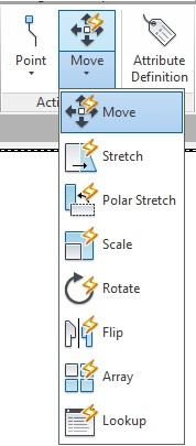
I'm not going to teach you how to create dynamic blocks; there are plenty of resources available on the Internet for that. I’m going to tell you how I put them to use. I started with dynamic blocks soon after getting AutoCAD 2015 up and running. I’ve not had a chance to fully explore all that they have to offer (so much to learn, so little time). Still, their impact has been significant.
Lazy Dino Days
But, let’s back up a little bit. I confess to being lazy, in fact I work hard at being lazy. The harder I work at laziness, the lazier I am. That’s why early on when establishing my machine design business I opted to go 3D. My reasoning was the machines I usually design are made up of rather simple shapes, such as square or rectangular bars and plates, cylindrical shafts and rods, etc. To clearly define a shape in 2D, you often need three orthographic views of an object — top, front, and side views. In order to define a plate, this requires drawing three properly aligned rectangles, each of which require two points to define the size. That’s six pick points (unless you copy and stretch geometry — there are a number of ways to get the desired result).
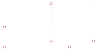
On the other hand by constructing a 3D object, only two points are needed to define the plate.
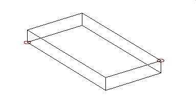
From this 3D object, AutoCAD takes over to create the three views (or whatever is required) by several means that are available. I’ll cover those methods in another article. This is a really simple part but by adding complexity to the part, each feature takes roughly a third of the effort to create. Perfect for a lazy Dino.
I imagine you are asking, “What the heck does this have to do with blocks?"
Well, I’m glad you asked Dear Reader. I applied the same logic to my blocks. As an example, a plate doesn’t do a whole lot by itself, it often has other components mounted to it, or it attaches to another part, needing clearance or tapped holes. So, I made a hole block, and I made it one unit in diameter.
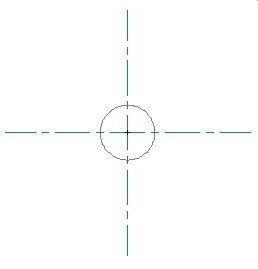
That’s not too exciting, so I added the hole side view
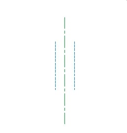
OK, so that’s not very exciting either, but I added the two together as nested blocks, copying and rotating the side block, creating a pseudo 3D block that when inserted provides top, front, and side views.
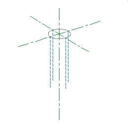
With this stroke of genius (hey, I’m a dinosaur) I could insert one 3D hole and it was represented in all standard orthographic projections. My method to create the projected views employed Solview, Soldraw, and Solprof, plus a custom AutoLISP routine. I then exploded the 3D inserts and erased the nested blocks that were not needed for display. However, there was a downside to this because the displayed side holes were fixed in length. This meant that after projecting my view, I often had to explode the side insert and then trim or extend the geometry.
Enter Dynamic Blocks
Now with dynamic blocks at my disposal I can rethink my process, increase my speed, and end up with a better result. By recreating my side hole block with a stretch parameter that lengthens the hidden sidewall lines and the center line, I can easily modify the lengths of the remaining inserts once the 3D insert is exploded. Here you can see the side hole block after selection, which shows the arrowed grip allowing the stretch action. Did I mention I love those stretch arrow grips?
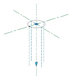
I can't seem to perform a stretch operation on multiple inserts with a crossing window. This left me somewhat disappointed, but as with so many AutoCAD features there are numerous ways to accomplish the end goal. I am able to grip multiple arrows to make them hot, and then stretch them or once I know the length, I can easily change the parameter in the Properties palette.
I'm frustrated I can't assign a z-value to my dynamic blocks. But I can always write an AutoLISP routine for that. I’ve still got some challenges ahead of me to fully engage with dynamic blocks, but challenges are what I live for
Rawrrr!
Dynamic blocks are truly powerful AutoCAD objects that are having a profound impact on my machine design. The above is a very simplified example of my ongoing investigation of AutoCAD 2015’s capabilitiesnd a good indication of what’s in store for me as I progress out of the swamp.
_________________
About the author: Patrick Hughes, machine designer and owner of Engineered Design Solutions in Rockford, Illinois, has worked with AutoCAD since 1991. He has developed a number of AutoLISP and other software solutions to automate his workflow and increase productivity, including the commercially available time tracking program, CadTempo.


